The Dynaco Tube Audio Forum

Would you like to react to this message? Create an account in a few clicks or log in to continue.
The Dynaco Tube Audio Forum

Dedicated to the restoration and preservation of all original Dynaco tube audio equipment - Customer support for Tubes4hifi VTA tube amp and preamp kits and all Dynakitparts.com products


+37
fedoragent
Dale Stevens
KenGaler
Wharfcreek
Tubes4ever
Peter W.
deepee99
rjpjnk
ejc
Dave_in_Va
GreggW
gener8r
neali
Jim McShane
Pat R.
heyraz
GP49
dmtparker
arledgsc
MexicoMike
stewdan
Ed Rosenberger
telefunking
scottlowe
guentherj2
ricohman
corndog71
sKiZo
Maintarget
poconoman
burnedfingers
Feistygoat
mantha3
Bob Latino
anbitet66
pmit2188
Roy Mottram
41 posters

    tube rectifier "yellow sheet" diode mod

    heyraz
    heyraz


    Posts : 59
    Join date : 2011-10-26

    tube rectifier "yellow sheet" diode mod - Page 3 Empty Re: tube rectifier "yellow sheet" diode mod

    Post by heyraz Sun Dec 07, 2014 10:25 pm

    When using 2 diodes in series like this (referring to post 15), it is best to use resistors (something like 330k) across each one to be sure they "share the load" equally.

    I've seen that done with identical electrolytic capacitors in series ( halves the uf while doubling the voltage rating) but I don't think it applies to diodes.  The purpose of the diode is to act as a "one way switch", sort of a backflow preventer.  Bridging a resistor across the diode would afford an easy path back.  
    Two diodes in series doubles the inverse voltage protection and causes a slight forward voltage drop.
    dmtparker
    dmtparker


    Posts : 14
    Join date : 2014-09-25
    Location : Bocas del Toro, Panama

    tube rectifier "yellow sheet" diode mod - Page 3 Empty Re: tube rectifier "yellow sheet" diode mod

    Post by dmtparker Mon Dec 08, 2014 8:47 am

    I've seen that done with identical electrolytic capacitors in series ( halves the uf while doubling the voltage rating) but I don't think it applies to diodes.  The purpose of the diode is to act as a "one way switch", sort of a backflow preventer.  Bridging a resistor across the diode would afford an easy path back.  
    Two diodes in series doubles the inverse voltage protection and causes a slight forward voltage drop.
    If you look at http://www.curcioaudio.com/ST7-CAP2-sch.jpg you can see this is not my original idea. Load sharing by using high ohmage resistors is common practice. One unrelated thing to note is that also in this diagram, Curcio used unequal resistors to balance caps of unequal value, a practice they later abandoned.


    Last edited by dmtparker on Tue Dec 09, 2014 8:18 am; edited 1 time in total (Reason for editing : Fixed link)
    heyraz
    heyraz


    Posts : 59
    Join date : 2011-10-26

    tube rectifier "yellow sheet" diode mod - Page 3 Empty Re: tube rectifier "yellow sheet" diode mod

    Post by heyraz Mon Dec 08, 2014 11:15 pm

    Your link didn't work. But what I did find looked like Curcio's solid state design to replace the 5AR4 vacuum tube rectifier. (4 diodes, 4 resistors after T1-T1).
    The 5AR4 rectifier is a soft start device, the resistors in Curcio's circuit help mimic the vacuum tube by softening the otherwise immediate solid state start.
    avatar
    GP49


    Posts : 792
    Join date : 2009-04-30
    Location : East of the sun and west of the moon

    tube rectifier "yellow sheet" diode mod - Page 3 Empty Re: tube rectifier "yellow sheet" diode mod

    Post by GP49 Tue Dec 09, 2014 1:40 pm

    The four resistors act more to compensate for the lower voltage drop of the diodes as compared to the 5AR4, reducing the B+ voltage. The only "slow start" characteristic that results from them is that it would take a few centiseconds longer to charge up the filter capacitors and apply B+ to the tubes.
    heyraz
    heyraz


    Posts : 59
    Join date : 2011-10-26

    tube rectifier "yellow sheet" diode mod - Page 3 Empty Re: tube rectifier "yellow sheet" diode mod

    Post by heyraz Tue Dec 09, 2014 2:25 pm

    The four resistors act more to compensate for the lower voltage drop of the diodes as compared to the 5AR4, reducing the B+ voltage. The only "slow start" characteristic that results from them is that it would take a few centiseconds longer to charge up the filter capacitors and apply B+ to the tubes.

    Right...Apples and Oranges for this particular discussion.
    The so called "tube diode rectifier mod" under discussion has to do with protecting the 5ar4 tube from flashing over should the power from the mains drop and then suddenly come back on.  In that situation, the diodes are placed after the rectifier and before the storage capacitor, preventing the charge in the capacitor from discharging backwards into the 5ar4 tube. For this application, dropping resistors serve no purpose as the tube rectifier is providing the voltage, the diodes after them are only slightly dropping the voltage while they prevent flashback. I see no need for balancing resistors. In fact, balancing resistors for this application seems to nearly defeat the purpose of the tube rectifier diode mod. Wouldn't you agree?
    arledgsc
    arledgsc


    Posts : 496
    Join date : 2012-11-30
    Age : 70
    Location : Santa Rosa CA

    tube rectifier "yellow sheet" diode mod - Page 3 Empty Re: tube rectifier "yellow sheet" diode mod

    Post by arledgsc Thu Dec 11, 2014 11:59 am

    In the ST-120 I would consider using single 1N4008 diodes. They are rated 1200V pk inverse voltage versus 1000V for the 1N4007. And they are cheap as well.
    Pat R.
    Pat R.


    Posts : 57
    Join date : 2015-02-26
    Location : SE Pennsylvania

    tube rectifier "yellow sheet" diode mod - Page 3 Empty Re: tube rectifier "yellow sheet" diode mod

    Post by Pat R. Thu Feb 26, 2015 9:50 am

    Glad to have found this thread! Great information. I am finishing up a build of a VTA ST 70 and have made this mod to the rectifier..

    I also have a pair of Heathkit W4's that I have heavily modified including upgrading the power supply and converting to a 5AR4 rectifier to give soft start to the amps.. Since it looks like it is the reverse current from (especially) upgraded power supplies that takes out the 5AR4 I can only assume that this mod is useful in any amp using the 5AR4 with an upgraded power supply.. or on any 5AR4 amp..

    On an audio asylum thread there is much discussion about the short life of newer 5AR4 rectifiers.. citing that the new ones cannot handle the current of modern xformers.. especially when compared to certain vintage rectifiers like the old Mullards..


    Is this mod we are talking about and using, the thing to correct this problem overall ? Will this effectively extend the life of even a modern 5AR4 and not just protect it from a reverse current situation. (is this really what kills the tube prematurely?)
    avatar
    Jim McShane


    Posts : 237
    Join date : 2011-10-19
    Location : South Suburban Chicago

    tube rectifier "yellow sheet" diode mod - Page 3 Empty Re: tube rectifier "yellow sheet" diode mod

    Post by Jim McShane Fri Mar 13, 2015 3:10 pm

    Many of the people who generalize about "modern" 5AR4/GZ34s are unaware how much better the Genalex U77 and the 5AR4 Tung-Sol reissue are as compared to the Sovtek or Chinese/Shuguang. The Genalex and Tung-Sol (and probably the new Mullard too but I don't carry them) are far better tubes and IMHO the days of searching for old stock 5AR4s are over. These new tubes do a GREAT job, and I've had ZERO issues with them.
    avatar
    neali


    Posts : 8
    Join date : 2015-04-03

    tube rectifier "yellow sheet" diode mod - Page 3 Empty Re: tube rectifier "yellow sheet" diode mod

    Post by neali Wed Apr 08, 2015 11:02 am

    My first post so be gentle. I am interested in purchasing either an ST120 or two M125 kits from Bob with my tax refund money. The decision on which to buy will probably be made by she who must be obeyed. Smile

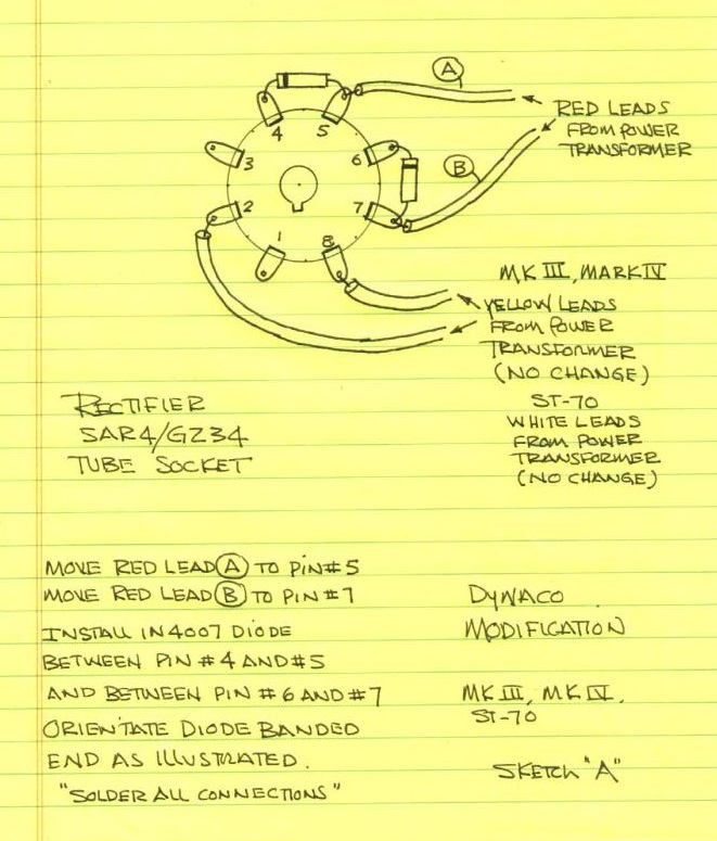
    But the reason I am posting in this thread, after a lot of reading, is that I have been thinking about this mod, the two diodes inserted before the rectifier tube, and it doesn't make a lot of sense to me. Here is why:

    The maximum PIV of the GZ34 is 1500V. The maximum PIV of the 1N4007 is only 1000V. So the GZ34 will do a good job of protecting the 1N4007. Right?

    The forward voltage portion of the AC sine wave does not stress a rectifier tube unless current is excessive in which case the power transformer is vulnerable as well. It is reverse voltage that can cause flashover. And the reverse voltage across the GZ34 will be virtually the same whether the 1N4007 is there or not because the reverse resistance of the GZ34 will be much higher than that of the series silicon rectifier which will form a voltage divider and the GZ34 will drop almost all the inverse voltage whether or not the silicon rectifier is there or not.

    Now does using series balanced diodes help? A little, it will increase the PIV of the diode pair to 2000V protecting the diodes from failing, but still not protecting the GZ34 from a reverse voltage flash over.

    My conclusions are placing the 1N4007s in series with the plates of the GZ34 is OK if you wish and if it gives you a feeling of confidence, fine. There is no possible damage from doing this. But I don't think there is any real benefit either.


    Further, I think there may be some benefit from adding a single series balanced pair after the rectifier tube to provide protection from the ON - OFF - ON rapid cycle.

    In my case, I am going to be using some NOS NIB Mullard Blackburn GZ33's or one if the ST120 is the choice. I am going to combine that with Bob's delay circuit board and use a Tower Manufacturing 30339015 15 amp GFCI 5-Outlet Adapter which will prevent ON - OFF - ON as this GFCI requires a manual reset to restore power.

    I am still considering placing the series balanced diodes after the GZ34 (GZ33 in my case) and welcome any advice from this forum. I also welcome any critique of my post and reasoning. Even flames. Smile
    avatar
    Jim McShane


    Posts : 237
    Join date : 2011-10-19
    Location : South Suburban Chicago

    tube rectifier "yellow sheet" diode mod - Page 3 Empty Re: tube rectifier "yellow sheet" diode mod

    Post by Jim McShane Wed Apr 08, 2015 12:53 pm

    I'll be kind! First off, there is nothing "balanced" about the diodes. The diodes simply rectify the AC wave and therefore the rectifier tube never sees the large peak inverse voltage that it would normally see. Without the diodes the rectifier tube could be exposed to the difference between the B+ volts (say 450 volts) and the most negative AC voltage it sees when the sine wave is at its most negative point. That depends on the secondary voltage of the trafo, but 350 volts would not be uncommon. So the rectifier tube sees a net difference of 450 plus 350, or 800 volts. This was more than some of the current production GZ34s could take without flashing/arcing. With the rectifiers ahead of the rectifier tube they never see any of the AC negative voltage swing, they only see pulsating DC. So the maximum difference is under 450 volts (or whatever the B+ voltage is in that particular amp). This made it possible for the Sovtek and Shuguang/Chinese 5AR4s to survive. Fortunately the recently released new Tung-Sol and Genalex reissue rectos (and I suspect the new Mullard reissue as well) are much better tubes.

    That's what the diodes are for, they do it well.


    Last edited by Jim McShane on Thu Apr 09, 2015 11:46 am; edited 1 time in total (Reason for editing : Edited to clarify concept)
    gener8r
    gener8r


    Posts : 61
    Join date : 2012-04-28

    tube rectifier "yellow sheet" diode mod - Page 3 Empty Re: tube rectifier "yellow sheet" diode mod

    Post by gener8r Wed Apr 08, 2015 8:10 pm

    Just got in a Mullard re-issue 5AR4, one of the New Sensor variables out there along with that Tung Sol and Genelex.   Other than pricing schedules I doubt there's much difference between them as they're all made at the same factory.  There does seem to be a difference between this Mullard/New Sensor Russian specimen and the Chinese variants I've tried, and also the JJ, both of which cannot take more than one arc.  

    Since placing the diode mod on the ST70s I have I can now use these less expensive tubes as none have failed coupled with the two diodes.
    Of course nothing beats a vintage Mullard for longevity, and they easily handle the voltage swing even without the MOD.  
    However, this MOD is a no brainer no matter what mfg. rectifier being used and at this point it should be standard in any build.
    avatar
    neali


    Posts : 8
    Join date : 2015-04-03

    tube rectifier "yellow sheet" diode mod - Page 3 Empty Re: tube rectifier "yellow sheet" diode mod

    Post by neali Wed Apr 08, 2015 10:29 pm

    Thank you Mr. McShane,

    You and your tubes have been highly recommended at forums that I frequented before I found this one.

    So, you say that reproduction 5AR4's failed at a PIV of 620 volts. That was not something I considered. I figured some L di/dt pulse killed the tube rectifier and that the tube met spec. If 620V PIV killed a poorly made repo, I can see why the mod would help. Thanks for taking the time to educate me and for being kind. Smile Still not sure that I understand the exact failure mode of a tube rectifier but I did have a Sovtek flash over. I will be in touch for some KT88's. Thanks.
    avatar
    Jim McShane


    Posts : 237
    Join date : 2011-10-19
    Location : South Suburban Chicago

    tube rectifier "yellow sheet" diode mod - Page 3 Empty Re: tube rectifier "yellow sheet" diode mod

    Post by Jim McShane Thu Apr 09, 2015 11:53 am

    First off it is NOT the reissue 5AR4s that failed. The new Tung-Sol and Genalex have been bulletproof. It's the Sovtek and Shuguang/Chinese that have failed

    Second, I just went back and edited my post to use more real world numbers. The AC voltage of 170 volts in my example was too low - senior moment I guess! Rolling Eyes  

    Please re-read the post now as it is now more "real world" in the voltages I used. The difference is more typically 800 volts or so, not 620. My apologies for the error. The concept of how the diodes work was right on the money as I described it - but my example needed improvement!
    avatar
    Guest
    Guest


    tube rectifier "yellow sheet" diode mod - Page 3 Empty Re: tube rectifier "yellow sheet" diode mod

    Post by Guest Sat May 09, 2015 11:14 am

    .


    Last edited by PeterCapo on Fri Dec 04, 2020 1:53 pm; edited 3 times in total
    avatar
    neali


    Posts : 8
    Join date : 2015-04-03

    tube rectifier "yellow sheet" diode mod - Page 3 Empty Re: tube rectifier "yellow sheet" diode mod

    Post by neali Thu Jun 04, 2015 1:21 pm

    Jim McShane wrote:First off it is NOT the reissue 5AR4s that failed. The new Tung-Sol and Genalex have been bulletproof. It's the Sovtek and Shuguang/Chinese that have failed

    Second, I just went back and edited my post to use more real world numbers. The AC voltage of 170 volts in my example was too low - senior moment I guess! Rolling Eyes  

    Please re-read the post now as it is now more "real world" in the voltages I used. The difference is more typically 800 volts or so, not 620. My apologies for the error. The concept of how the diodes work was right on the money as I described it - but my example needed improvement!

    Hi Jim,

    Do you (or anyone else) see any issues using the BY448GP-E3/54 diodes for the mod? I like the PIV. And I have some.

    http://www.vishay.com/docs/88543/by448gp.pdf
    GreggW
    GreggW


    Posts : 80
    Join date : 2015-07-15

    tube rectifier "yellow sheet" diode mod - Page 3 Empty Re: tube rectifier "yellow sheet" diode mod

    Post by GreggW Sun Sep 20, 2015 6:30 pm

    I've got some 1N4007 diodes in transit. After they're installed, what should the voltage readings be on pins 4 and 6?
    Bob Latino
    Bob Latino
    Admin


    Posts : 3263
    Join date : 2008-11-26
    Location : Massachusetts

    tube rectifier "yellow sheet" diode mod - Page 3 Empty Re: tube rectifier "yellow sheet" diode mod

    Post by Bob Latino Sun Sep 20, 2015 6:38 pm

    Hi Gregg,

    If you have a VTA ST-120, you should get between 400 VAC to maybe 430 VAC from pin 4 to chassis ground and about the same from pin 6 to chassis ground. If you have an ST-70, you should get about about 355 to maybe 375 VAC off each pin to chassis ground. The actual voltage you get will be determined by your incoming AC line voltage.

    Bob
    GreggW
    GreggW


    Posts : 80
    Join date : 2015-07-15

    tube rectifier "yellow sheet" diode mod - Page 3 Empty Rectifier mod - tying 4 and 6 together

    Post by GreggW Fri Oct 30, 2015 9:35 pm

    Didn't want to start a new thread... First, after three good weeks of running the 5V3A in the ST 120, it is flawless. It doesn't light up as cool as a 5AR4, but that's okay. I'm thinking of adding the series diodes (1N4007) to pins 4 and six of the rectifier tube, then tying pins 4 and 6 together. I've read the AK threads on the subject but haven't heard of anybody actually tying the pins together and flipping the switch. The other benefit besides increased current capability appears to be a drop in voltage reduction by half. For the 5V3A, that would cut it from 44 to 22, just 5 volts more than a 5AR4. I doubt my 66-year old ears could hear the difference in the higher B+, but some likely could. If those diodes ever failed, it would probably be a spectacular light show......
    GreggW
    GreggW


    Posts : 80
    Join date : 2015-07-15

    tube rectifier "yellow sheet" diode mod - Page 3 Empty Re: tube rectifier "yellow sheet" diode mod

    Post by GreggW Fri Oct 30, 2015 10:49 pm

    That .05 uf capacitor is the ceramic disc type, correct?
    avatar
    Guest
    Guest


    tube rectifier "yellow sheet" diode mod - Page 3 Empty Re: tube rectifier "yellow sheet" diode mod

    Post by Guest Sat Oct 31, 2015 7:44 am

    .


    Last edited by PeterCapo on Mon Nov 30, 2020 9:53 pm; edited 1 time in total
    Dave_in_Va
    Dave_in_Va


    Posts : 443
    Join date : 2013-04-02
    Location : Mid. VA

    tube rectifier "yellow sheet" diode mod - Page 3 Empty Re: tube rectifier "yellow sheet" diode mod

    Post by Dave_in_Va Tue Jul 05, 2016 9:59 am

    I've re-read this thread and it seems that the advantage of the diode mod is to protect the 5AR4 in case of power on/off blips.
    I have a VTA ST-70 and I use a Sylvania 5AR4 and the entire system in plugged into one of the Skizo recommended non-latching GFI gizmos. It kicks out when there is a power interruption and I have to manually reset it.
    So, am I right in thinking I don't have to worry about this diode mod?
    Roy Mottram
    Roy Mottram
    Admin


    Posts : 1837
    Join date : 2008-11-30

    tube rectifier "yellow sheet" diode mod - Page 3 Empty Re: tube rectifier "yellow sheet" diode mod

    Post by Roy Mottram Tue Jul 05, 2016 12:58 pm

    Hi Dave,
    yes, the diode mod is for protection, it doesn't do much of anything else. Seems that with your Skizo mod you're likely accomplishing the same protection.
    But for most people 40c worth of diodes is cheap protection for a $20 rectiifier, let alone any other tubes downstream . . .
    avatar
    ejc


    Posts : 33
    Join date : 2010-10-16
    Age : 73
    Location : Connecticut

    tube rectifier "yellow sheet" diode mod - Page 3 Empty Re: tube rectifier "yellow sheet" diode mod

    Post by ejc Sun Dec 04, 2016 1:48 pm

    tubes4hifi wrote:this is a common topic and search, so it'll be easier to find now
    this mod should be done to all tube amps using tube rectifiers, to reduce the chance of damaging the tube rectifier

    tube rectifier "yellow sheet" diode mod - Page 3 TubeRectifier-DiodeMod


    If I might ask a question.
    The diode mod for the rectifier tube is in addition to the diode to replace the selenium rectifier, not in lieu of?
    Roy Mottram
    Roy Mottram
    Admin


    Posts : 1837
    Join date : 2008-11-30

    tube rectifier "yellow sheet" diode mod - Page 3 Empty Re: tube rectifier "yellow sheet" diode mod

    Post by Roy Mottram Sun Dec 04, 2016 2:36 pm

    the diode mod for the rectifier tube (B+ circuit) has nothing at all to do with the diode replacing the old selenium rectifier for the bias circuit.
    avatar
    ejc


    Posts : 33
    Join date : 2010-10-16
    Age : 73
    Location : Connecticut

    tube rectifier "yellow sheet" diode mod - Page 3 Empty Re: tube rectifier "yellow sheet" diode mod

    Post by ejc Sun Dec 04, 2016 2:55 pm

    Thanks

    Sponsored content


    tube rectifier "yellow sheet" diode mod - Page 3 Empty Re: tube rectifier "yellow sheet" diode mod

    Post by Sponsored content


      Current date/time is Thu May 09, 2024 4:15 pm