Hullo All,
I recently completed an amp build; VTA Dynakit Mk III. Could use some assistance, first time - bone head alert, so please be gentle..
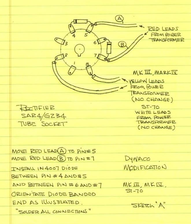
Without the rectifier in, getting filament power, all tubes light up. With rectifier, uh-oh, mechanical hum and fuse pops within seconds.
According to info here that could mean power trafo miswire.. Any suggestions welcome. Tried to post photo link this post. Hopefully the link will work to photo.
Maybe those with exp.'d eyes can spot obvious errors... or else recommend where to start to troubleshoot. Thanks again, for any help
to this novice builder.
K.
Mk III photo
I recently completed an amp build; VTA Dynakit Mk III. Could use some assistance, first time - bone head alert, so please be gentle..
Without the rectifier in, getting filament power, all tubes light up. With rectifier, uh-oh, mechanical hum and fuse pops within seconds.
According to info here that could mean power trafo miswire.. Any suggestions welcome. Tried to post photo link this post. Hopefully the link will work to photo.
Maybe those with exp.'d eyes can spot obvious errors... or else recommend where to start to troubleshoot. Thanks again, for any help
to this novice builder.
K.
Mk III photo
Last edited by Dingojazz on Sat Mar 08, 2014 1:58 pm; edited 1 time in total