The Dynaco Tube Audio Forum

Would you like to react to this message? Create an account in a few clicks or log in to continue.
The Dynaco Tube Audio Forum

Dedicated to the restoration and preservation of all original Dynaco tube audio equipment - Customer support for Tubes4hifi VTA tube amp and preamp kits and all Dynakitparts.com products


5 posters

    C9-10 Question

    avatar
    Guest
    Guest


    C9-10 Question Empty C9-10 Question

    Post by Guest Wed Feb 18, 2009 11:26 pm

    I am about to try out the k40ys in my vta70 board, along with a few riken resistors. I was checking the install manual on this site and noticed that the parts list says not used for c9-10 (47 uf-50v).
    Has the board changed?
    If not should these be pulled?
    Also can I get away with soldering the k40s from the bottom?
    Great forum, Richard
    Bob Latino
    Bob Latino
    Admin


    Posts : 3263
    Join date : 2008-11-26
    Location : Massachusetts

    C9-10 Question Empty Re: C9-10 Question

    Post by Bob Latino Thu Feb 19, 2009 9:14 am

    Richard,

    I will let Roy (tubes4hifi) who designed the VTA driver board comment on C9, C10 when he gets a chance ..

    The Russian K40-Y capacitors may be installed from the bottom of the board. I don't know if you have the larger 1000 volt caps that I use but installation should be about the same.

    Instructions are below.

    If you are replacing the existing four main coupling caps on the driver board and it is not necessary to remove the driver board to replace the caps. Remove all tubes from the amp. Remove the bottom cover and then stand the amp on the bottom binding posts with the top of the amp on your RIGHT and the inside of the amp on your LEFT. Heat the INSIDE solder connection of each coupling cap from the top of the driver board with your RIGHT hand as you pull on the cap’s INSIDE connection with your LEFT hand. Apply constant pressure with your LEFT hand and the INSIDE cap lead will pull out when the solder connection turns to a liquid. Now stand the amp upside down with the inner wiring facing you. Heat the OUTSIDE connection of each cap from the INSIDE of the chassis and pull the cap that was in there out.

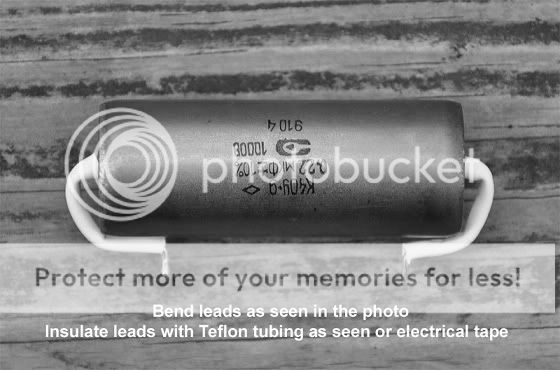
    C9-10 Question RussianPIO

    When you install the new Russian PIO caps bend the leads as shown in the photo above and insulate the leads with shrink tubing or electrical tape. Solder in the OUTSIDE lead of each Russian PIO caps FIRST from the inside of the amp. The INSIDE lead of each cap should be installed by heating the solder connection from the TOP of the board and pressing the cap lead in against the eyelet from the bottom. When the solder turns to a liquid the cap lead will slide into the eyelet.

    Bob
    Roy Mottram
    Roy Mottram
    Admin


    Posts : 1837
    Join date : 2008-11-30

    C9-10 Question Empty C9 & C10

    Post by Roy Mottram Thu Feb 19, 2009 12:09 pm

    Hi Richard,
    the circuit is the same for 20 years now, however, the PCB has had a few minor changes over the past couple years to make room for larger capacitors, etc.
    C9 & C10 are commonly used in this type of circuit to increase the gain by bypassing the cathode resistor on the first gain stage. However, due to feedback from customers and from additional research on circuit design, C0 & C10 are not actually needed. By removing them, there is a slight benefit in reduced distortion as well as very slightly reduced gain. It's a small difference.
    As for the PIO output coupling caps, follow Bob's instructions, and let me add - be careful that the capacitor body does not touch anything else, such as the PCB traces, or the octal sockets/test points on the front of the amplifier.
    Roy
    avatar
    dodeca


    Posts : 8
    Join date : 2009-02-18
    Age : 72
    Location : Butte, Montana

    C9-10 Question Empty Re: C9-10 Question

    Post by dodeca Thu Feb 19, 2009 12:47 pm

    Thanks Roy,Bob, appreciate the help.

    Richard
    avatar
    dodeca


    Posts : 8
    Join date : 2009-02-18
    Age : 72
    Location : Butte, Montana

    C9-10 Question Empty Sound great!

    Post by dodeca Sat Feb 21, 2009 3:10 pm

    I finished the install late last night. Took a bit of rearranging, but otherwise went well. I put two bands of sorbothane around each cap to try and keep them up off the board, and they should help dampen any vibrations.
    About 11 hours of break in and these pios sound great. Previously had sonicaps gen 1 and wasn't satisfied. The gen 2 are much better imho. Both sonicaps require at least 100 hours of play.
    Almost put in the Audiocap thetas-ppt. These are my favorite reasonably priced cap, but for now I'm extremely happy with the k40y-9s.
    I had JJ kt77s in this before and they do sound excellent, but 3 out of the six I bought do not hold a bias worth a damn! Recently bought a quad of Tung Sol reissue EL34bs and they sound at least as good as the JJs. Excellent bass, midrange, high end. Deep and wide sound stage, nice air with good recordings, esp. hdcds.
    Richard
    avatar
    dodeca


    Posts : 8
    Join date : 2009-02-18
    Age : 72
    Location : Butte, Montana

    C9-10 Question Empty Pics

    Post by dodeca Sat Feb 21, 2009 3:13 pm

    Forgot, posted pics in the Your Dynaco System. Richard
    avatar
    1973shovel


    Posts : 45
    Join date : 2009-12-13

    C9-10 Question Empty Re: C9-10 Question

    Post by 1973shovel Sun Dec 13, 2009 9:37 pm

    Roy wrote:

    "C9 & C10 are commonly used in this type of circuit to increase the gain by bypassing the cathode resistor on the first gain stage. However, due to feedback from customers and from additional research on circuit design, C0 & C10 are not actually needed. By removing them, there is a slight benefit in reduced distortion as well as very slightly reduced gain. It's a small difference."

    Damn, am I glad to read this. I was just pricing Black Gates or giant Russian caps to use for C9 & C10. Instead, I'll just remove the Panasonic FM's I have in there and be done with it.

    I'm going to like this forum!
    Bob Latino
    Bob Latino
    Admin


    Posts : 3263
    Join date : 2008-11-26
    Location : Massachusetts

    C9-10 Question Empty Re: C9-10 Question

    Post by Bob Latino Sun Dec 13, 2009 10:08 pm

    Hi,

    What Roy said is correct. The gain drops a fraction of a dB and the distortion will drop a fraction of a percent with C9 and C10 OUT of the circuit. Believe me, you cannot HEAR the difference WITH or WITHOUT C9 or C10 in the circuit. The theory here is of course > If a part isn't really needed then don't use it. For those that have a VTA boarded ST-70 right now with C9 and C10 IN the circuit > IMHO I would just leave it in there. They don't hurt anything and their removal won't really affect the sound in any meaningful way that you can really hear.

    Bob
    avatar
    defec


    Posts : 9
    Join date : 2010-12-19

    C9-10 Question Empty Re: C9-10 Question

    Post by defec Sun Dec 19, 2010 8:43 pm

    Hi, if I wanted to reinstall c9-10 for old times sake would a 35volt cap work okay? I have some around the house. Thanks
    Bob Latino
    Bob Latino
    Admin


    Posts : 3263
    Join date : 2008-11-26
    Location : Massachusetts

    C9-10 Question Empty Re: C9-10 Question

    Post by Bob Latino Sun Dec 19, 2010 8:55 pm

    Hi,

    That cap only looks at a few volts as part of the feedback circuit. I am sure that a 35 volt cap would work just fine.

    NOTE - For those that have the newer version of the VTA driver board in the past year or so you will find that there IS NO C9 or C10 on your board. C9 and C10 have been removed (because they were deemed as unnecessary) from newer VTA driver boards.

    Bob
    avatar
    defec


    Posts : 9
    Join date : 2010-12-19

    C9-10 Question Empty Re: C9-10 Question

    Post by defec Sun Dec 19, 2010 9:31 pm

    Thanks Bob. While we are on the subject of boards, I noticed that mine has a spot for some type of transistor in each channel. What was this used for originally?
    Bob Latino
    Bob Latino
    Admin


    Posts : 3263
    Join date : 2008-11-26
    Location : Massachusetts

    C9-10 Question Empty Re: C9-10 Question

    Post by Bob Latino Sun Dec 19, 2010 10:01 pm

    defec wrote:Thanks Bob. While we are on the subject of boards, I noticed that mine has a spot for some type of transistor in each channel. What was this used for originally?

    Hi,

    Not sure what you mean ? There are no transistors on the VTA driver board ? Can you show us a photo of what you mean ?

    Bob
    avatar
    defec


    Posts : 9
    Join date : 2010-12-19

    C9-10 Question Empty Re: C9-10 Question

    Post by defec Sun Dec 19, 2010 10:43 pm

    Sure, see it by VR5 and 6. The board traces make it look like a transistor. It's clearly on my board with traces going to it. I figured it may be for some type of Constant Current Source that got abandoned sometime in the past.

    C9-10 Question Vta702

    avatar
    defec


    Posts : 9
    Join date : 2010-12-19

    C9-10 Question Empty Re: C9-10 Question

    Post by defec Sun Dec 19, 2010 10:50 pm

    There's also a spot for another component to the side of it by C13 and 14 labeled RC.

    Sponsored content


    C9-10 Question Empty Re: C9-10 Question

    Post by Sponsored content


      Current date/time is Mon May 20, 2024 4:26 pm