
With this restoration I now have completed them for all of my Dynaco power amps. The MK VIs are the most complex and difficult of the family to do. From earlier posts you will see I keep my Dynaco amp restorations as close to stock as as possible. For most of the amps that is not hard as all the needed parts are available with a large selection of parts and vendors to choose from. The MK VIs do not have that type of support. The difficulties in order are 1) the 8417 tubes are no longer manufactured and finding two NOS quad matched sets is almost impossible and would be very expensive. 2) the 50 and 100 uF at 300 volts power supply caps with the same shape and mounting as the original were not available. All other parts were not a problem to source.
When purchased the previous owners had converted these amps to 6550 in lieu of the 8417. I had to determine how they made the conversion but felt I needed to stick with the 6550/KT88 family for a number of reasons. Tube availability primarily and the ability to try the KT77/EL34 family without further parts swapping. The front end circuit is the familiar Dynaco one with a few minor enhancements. Much is written about the need for more drive voltage from the front end after you make this conversion. I now feel this is not an issue with the traditional Dynaco front end circuit. More on this area in a different post.
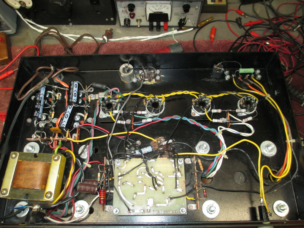
After much looking I gave up on the power supply caps in the original arrangement and evaluated doing them another way. Still keeping the same ratings but knowing they would have to mount differently. I settled on disconnecting all original caps but leaving them in place. Then mounting two terminal strips underneath and using the mounting holes/screws from the original caps. Purchasing axial lead caps of the same uF but slightly higher voltage gave me the same power supply capability but are now properly mounted, easily replaced in the future and work well.
Next up was the bias supply. When converted a previous tech had done a pretty good job of selecting resistors R104 and R102 so the adjustment pot was able to set the 6550 in their desired range. The values however put a different load on the power transformer than all the earlier amps. Dynaco used a little over 2 mA of load (on average) for the bias circuit in all their fixed bias amps. I used that value and set the center of adjustment pot for about -60VDC. That gave me new values of R102 and R104. Final test result were right on. It will not only adjust for the 6550s but the KT77/EL34 family as well.
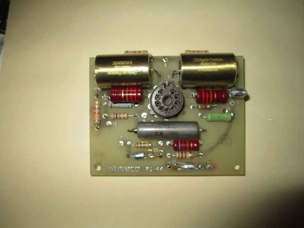
Two items I was not expecting but were able to resolve. One is on the circuit board you will find the global feedback resistor is labeled R13. However on the component values page there is no listing for R13!! It took a bit of investigating to determine and verify it should be a 3000 ohm resistor. Mine were two watt so I replaced them with those ratings. Another issue was resistor R101. The 240,000 ohm did not jump out as problem but the 1 watt rating was questionable. A simple calc and I feel this is underrated. It will just work but most electrical designers would opt for more wattage derating. Use a 2 watt (or higher) for good long term results. Not as big a deal as the R13 omission but still not what I would have expected from Dynaco.
The amps needed a good cleaning but the metal work did not need anything else done. Tube sockets were cleaned and tighten as needed. Good quality caps and carbon film resistors now on the circuit board. You have to have three hands at times to reach all the mounting screws and nuts with the way they mounted parts in this amp. It could have been a lot simpler but it is what it is. I could have rewired and made that look nicer but decided it was not worth it. The rest went well and they sound and work great.
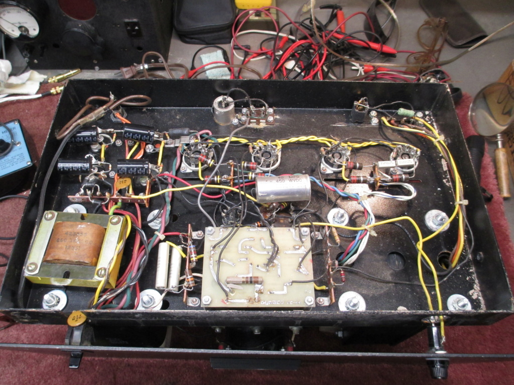
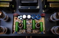
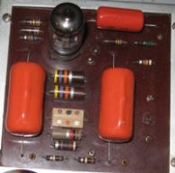
Pictures below are the top view without the cover which looks the same before and after. Then three demo and rebuild photos of the underneath. Final two of the completed amp. Both amps are almost identical so no need for more photos of the other one.
When purchased the previous owners had converted these amps to 6550 in lieu of the 8417. I had to determine how they made the conversion but felt I needed to stick with the 6550/KT88 family for a number of reasons. Tube availability primarily and the ability to try the KT77/EL34 family without further parts swapping. The front end circuit is the familiar Dynaco one with a few minor enhancements. Much is written about the need for more drive voltage from the front end after you make this conversion. I now feel this is not an issue with the traditional Dynaco front end circuit. More on this area in a different post.
After much looking I gave up on the power supply caps in the original arrangement and evaluated doing them another way. Still keeping the same ratings but knowing they would have to mount differently. I settled on disconnecting all original caps but leaving them in place. Then mounting two terminal strips underneath and using the mounting holes/screws from the original caps. Purchasing axial lead caps of the same uF but slightly higher voltage gave me the same power supply capability but are now properly mounted, easily replaced in the future and work well.
Next up was the bias supply. When converted a previous tech had done a pretty good job of selecting resistors R104 and R102 so the adjustment pot was able to set the 6550 in their desired range. The values however put a different load on the power transformer than all the earlier amps. Dynaco used a little over 2 mA of load (on average) for the bias circuit in all their fixed bias amps. I used that value and set the center of adjustment pot for about -60VDC. That gave me new values of R102 and R104. Final test result were right on. It will not only adjust for the 6550s but the KT77/EL34 family as well.
Two items I was not expecting but were able to resolve. One is on the circuit board you will find the global feedback resistor is labeled R13. However on the component values page there is no listing for R13!! It took a bit of investigating to determine and verify it should be a 3000 ohm resistor. Mine were two watt so I replaced them with those ratings. Another issue was resistor R101. The 240,000 ohm did not jump out as problem but the 1 watt rating was questionable. A simple calc and I feel this is underrated. It will just work but most electrical designers would opt for more wattage derating. Use a 2 watt (or higher) for good long term results. Not as big a deal as the R13 omission but still not what I would have expected from Dynaco.
The amps needed a good cleaning but the metal work did not need anything else done. Tube sockets were cleaned and tighten as needed. Good quality caps and carbon film resistors now on the circuit board. You have to have three hands at times to reach all the mounting screws and nuts with the way they mounted parts in this amp. It could have been a lot simpler but it is what it is. I could have rewired and made that look nicer but decided it was not worth it. The rest went well and they sound and work great.
Pictures below are the top view without the cover which looks the same before and after. Then three demo and rebuild photos of the underneath. Final two of the completed amp. Both amps are almost identical so no need for more photos of the other one.
  |